 |
| Email Home Page |
|
| Email Home Page |
|
|
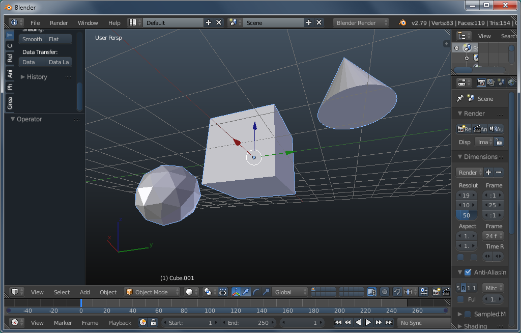
The bisect tool is used when you want to divide or cut an object. It allows you to draw a line across the object to set the cut point. For those who need precision, it may initially seem like there is no way to set the line perfectly straight or in a specific location. When the line is set, it's only a rough starting point. In the bisect dialog box at the bottom of the T-panel, after drawing the line, you can fine tune the location and angle of the line. This is an example of what it does. This first image is the object seen in OBJECT mode. This is ONE object since only one object (as recognized in OBJECT mode) since you have to select the object that you want to modify in EDIT mode. The cone and icosphere were added/created in EDIT mode.
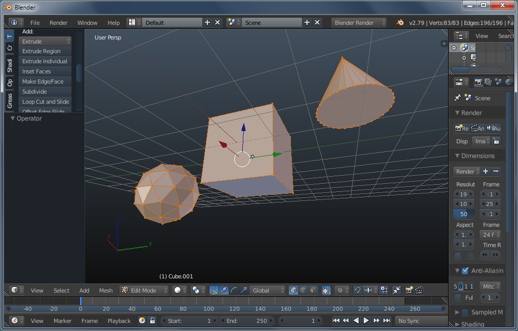
Below, you can see that all 3 objects were selected/highlighted. That's necessary if you want to make the cut across all of the individual objects. It only cuts what's selected.
If you only want to cut across part of what's in the workspace, select only its parts. Using the LASSO in WIREFRAME mode works the best. The lasso select is accessed with CTRL-RMB (if you've opted for an LMB click to select in the USER PREFERENCES section). Below, only the cube was selected so it was all that was bisected.
While they're visible, notice that the BISECT tool is in the TOOLS tab of the T-panel. The image shows a bisect line across the objects. It's a slightly different view than the others but the exact position wasn't critical for this.
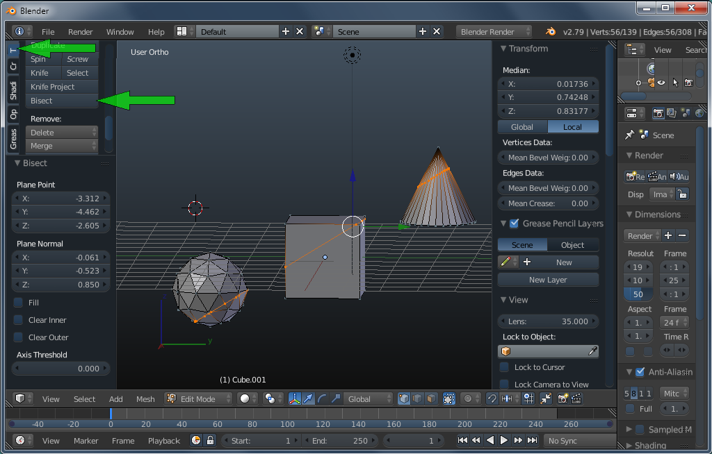
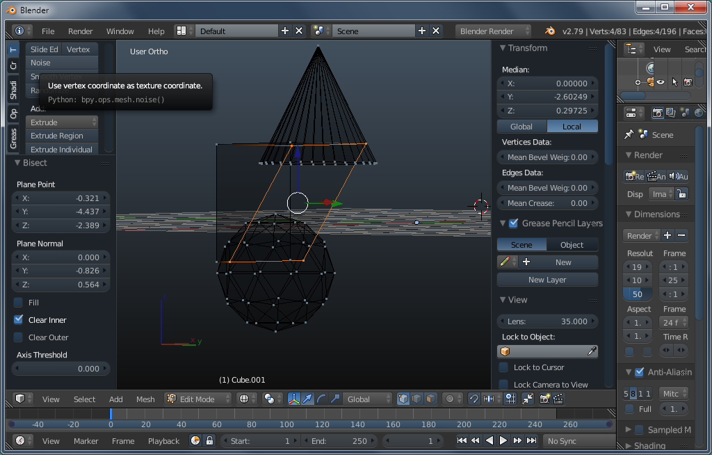
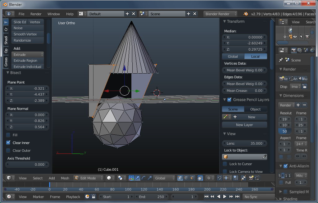
When bisecting, you have several options. They are listed in the bisect dialog box. They allow you to keep or discard the area that's on the top/bottom, left/right if the bisect line. For the next two images, make note of the box that's ticked in the lower left corner of the image. The view has been changed to allow you to see the remaining section better.
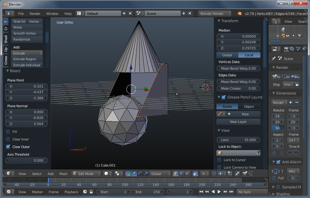
There is one more option that can be selected and that's to fill the open area with a face. This image shows how the edited object changed with that option chosen.
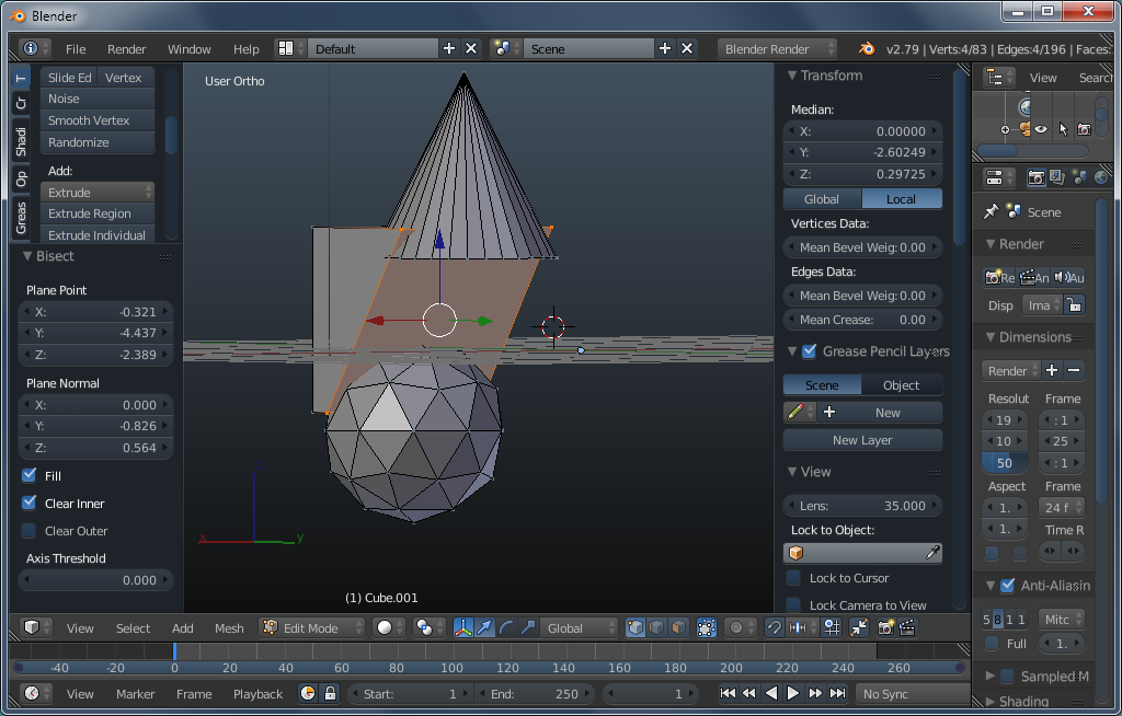
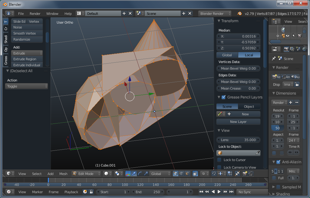
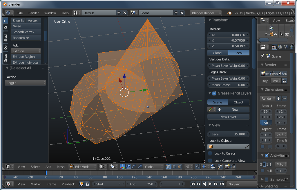
The next 2 are overlapping objects that were bisected. One is in normal (solid) mode, the other in wireframe mode. The wireframe is orange here instead of black because these objects are 'selected'.
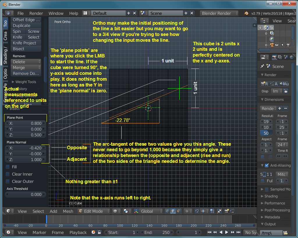
The following graphic gives a bit more insight as to what's happening in bisect mode. The image was getting too cluttered so the rest of the notes will have to be external. Looking at the two green crosses, the hashed one is on the x/y axis. This is the reference point for the values in the PLANE POINT text fields. The solid green cross is the point given by X and Z. The cross is 0.5 units up from the X axis, on the Z axis (Z value is 0.500) and 0.8 units to the right of the Z axis on the X axis (X value is 0.8). When the values in the PLANE NORMAL fields are changed, the plane will rotate around the center of the solid green cross.