 |
| Email Home Page |
|
| Email Home Page |
|
|
|
Part 3
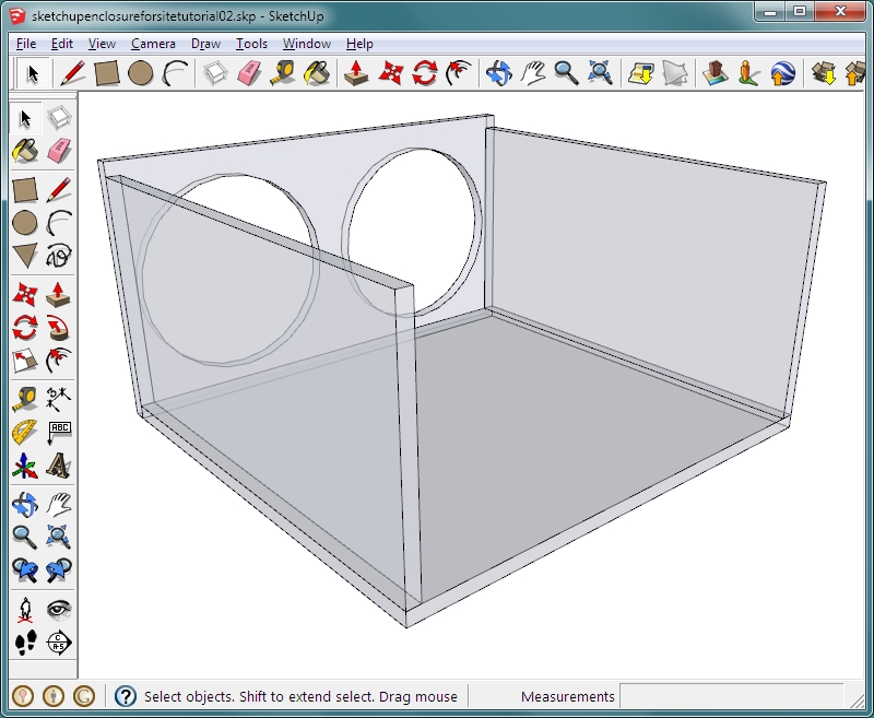
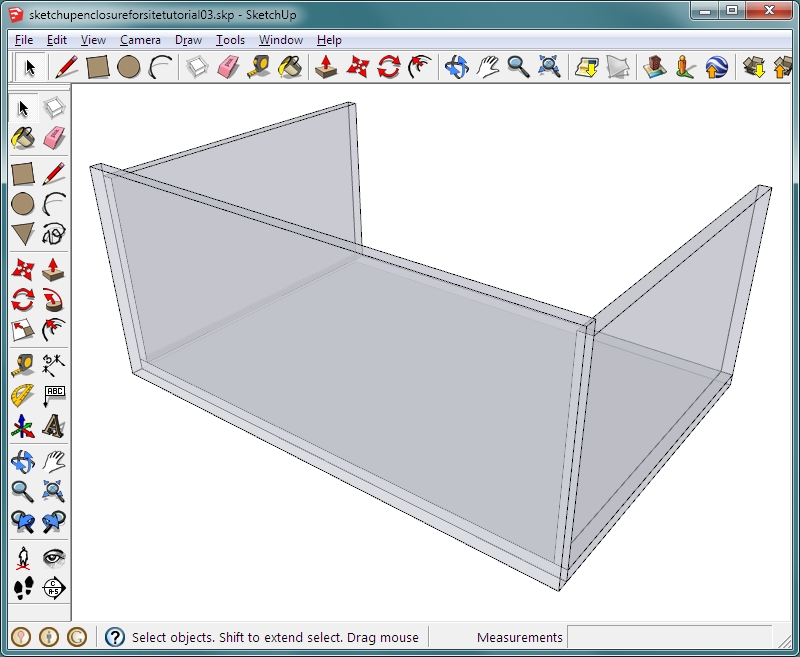
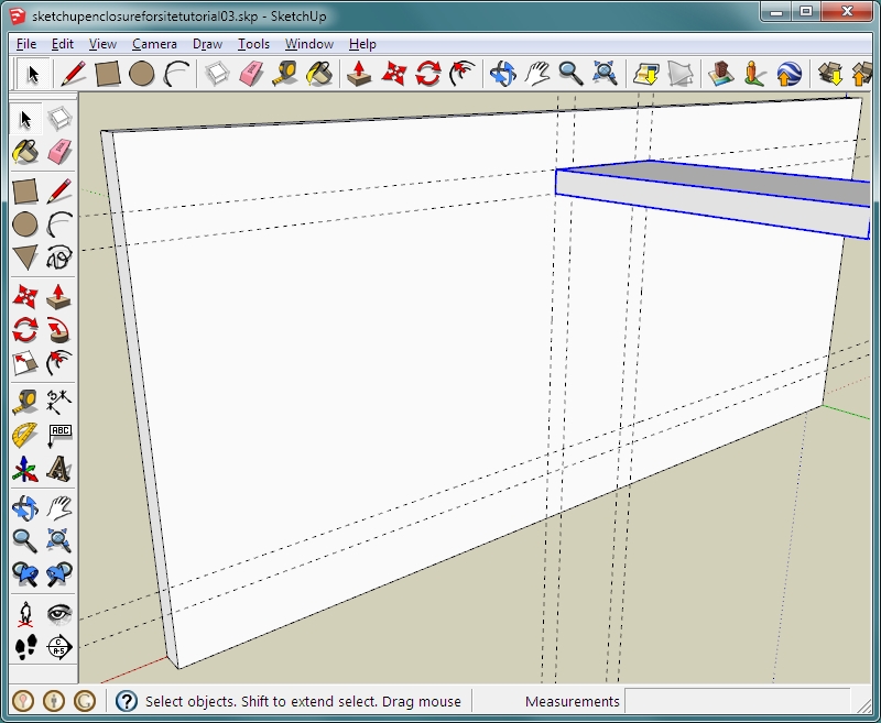
Let's go through another example to learn a few more ways to use Sketchup's features. We will start with the 2-12 enclosure above. Let's say that we want to add a port. Most people are using square ports so that's what we'll use here. I don't like using a wall of the enclosure as part of the port so this port will be located in the center of the front baffle. To make the port large enough to prevent port noise/turbulence, it will have to be relatively large. This means that the woofers will have to be farther apart and therefore, the enclosure will have to be wider. We will remove the divider so that we can use only one port. Open the 2-12 enclosure file. Orbit around so you can click on the top and the back boards of the enclosure (using the SELECT tool). Right-click each and select HIDE. You could also use the SELECT tool and select both enclosure panels then use the EDIT >> HIDE option. Select and delete the center divider.
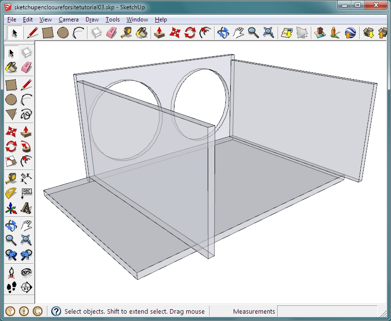
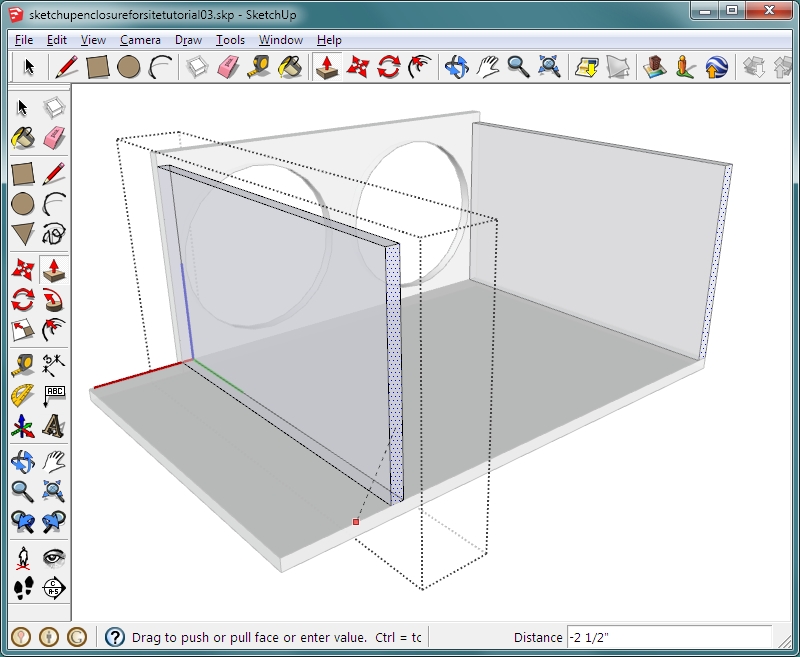
 Since the enclosure is going to have to be wider, it won't have to be as deep. Change the width of the bottom board to 32" wide. The change in dimensions isn't done to try to produce/retain a specific internal air volume. This is simply an example of how to use the features of Sketchup. Since the bottom board is a group, you will have to get into the group to use the push/pull tool. Click the SELECT tool and double-click the bottom board so that it shows a dashed box around the board. Now use the PUSH/PULL tool to pull the left end out. Click and release. Type 6 into the text field and hit ENTER. This will extend it by 6". Push the back of the bottom board in by 2.5" (click, release, enter value...).
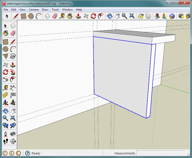
 Now you need to re-size the sides of the enclosure. You'll do it the same way as you did for the bottom (SELECT tool, double-click, PUSH tool). Since the bottom board is already the correct depth, you can use it as a reference. Sketchup uses 'inferences' to allow you to match angles, positions... When pushing, move the cursor over the top back edge of the bottom board. You will see a line connecting the side and the back edge of the board. When you see that, it means that it will be pushed to that point. When it's aligned with the edge, click to set the new size. Click the SELECT tool and either click outside the component or hit the ESCAPE button on your keyboard. Since both sides were the same 'component', both changed when you modified one.
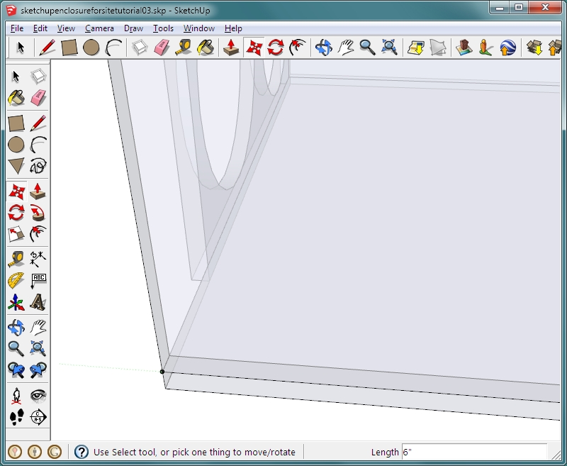
 Orbit and zoom until you can clearly see the front corner of the end of the enclosure and the bottom board. Choose the MOVE tool. Place your mouse cursor over the bottom, front corner of the end and notice that the red axis is aligned with the direction in which you need to move the board. Click that corner and then click the RIGHT ARROW on the keyboard. That will lock it to the red axis. Move that corner to the top corner of the bottom board.
 Now orbit and zoom until you can see the entire front baffle. Use the SELECT tool and double-click the baffle. Click all of the circles, starting with the ones in the rear. Click to highlight the outline of the circle and then hit the DELETE button. You could also use the erase tool. Now use the PUSH/PULL tool to extend the front baffle. Use the corner of the bottom board as the point on which to set the length. If you have trouble finding the edge, remember that you can zoom in with the mouse wheel while using other tools.
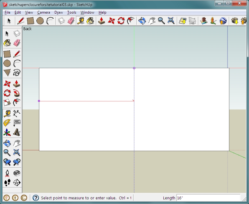
 Click the select tool. Select all objects by pressing ctrl-a or by dragging a box around everything on the screen. Now hold down the shift button and click the baffle. This will de-select the baffle. Now hide all other objects (EDIT >> HIDE). Choose the REAR camera position (CAMERA >> STANDARD VIEWS >> BACK). Go to the default display style (WINDOW >> STYLES >> choose DEFAULT). Choose the tape measure/guide line tool. Make a center guide line (click on left edge, move tip of tape measure over the top edge until you find the center (cursor changes from purple square to dot) and click. This will place a guide line. If it does not, make sure that the guides are turned on (VIEW >> GUIDES). Place a horizontal guide centered on the baffle (click top of board, hold cursor over the edge of the baffle until you find the center and click to set the guide line.
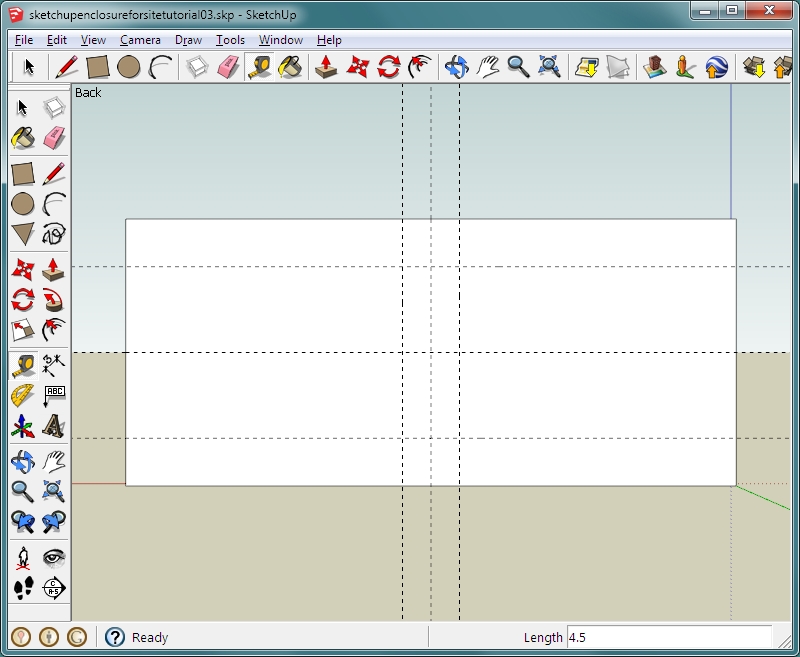
 The port will vary depending on the design of the enclosure. For this one, the port has a front opening of 3" by 9". It will be a total of 11.25" long. Since it's 3" wide, you know that there will be 1.5" on each side of the vertical center line. Using the guide line tool, make a guide 1.5" on each side of the center line (click and move in the desired direction, enter the value and hit enter). Do the same above and below the horizontal line. Since the port is 9" tall, you will need guide lines 4.5" above and below the horizontal line.
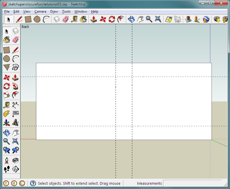
 Delete the center lines (select tool, click to highlight and hit delete). This is the outline of the port for the enclosure.
 To make the boards that make up the port, we will work from the guide lines. Here we will use 3/4" (0.75") material. If you wanted to use something thinner, 5/8" (0.625") for example, you would use the offset for that material. From the guide lines for the port, make four more guide lines 0.75" outside of the existing guides.
 Make a rectangle in the top section of the parallel guides and pull it out to 10.5" (enter 10.5 in text field). Triple-click it and then right-click it and select MAKE COMPONENT. Name it 'port top/bottom' and click CREATE. The port is 11.25" long but 3/4" is the front baffle. That's why we only have to pull the rectangles out 10.5".
 Now create the side board for the port in the same way. Create a component named 'port side'.
 For the other two sides of the port, you can simply copy and paste the two you have now. For the top, use the SELECT tool to select it. Select the MOVE tool, hold the control button down and click the top front corner. Release the control button and press the UP ARROW button. This will lock it to the blue axis. Move it down until it locks to the bottom front corner of the side port board.
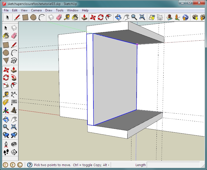 Do the same thing for the side board (select, MOVE tool, hold control button to duplicate when moving, release control button and hit RIGHT ARROW to lock the red axis). When you have all four boards, use the select tool to select all of them (hold SHIFT key and click all four. Right-click and select MAKE GROUP. Now right-click on the group and select HIDE.
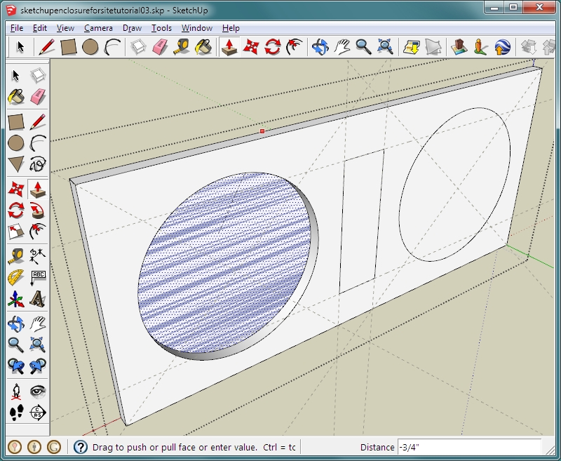
 Delete the outside guide lines, leaving only those that represent the center of the port. Change the camera to BACK (CAMERA >> STANDARD VIEWS >> BACK). Click the ZOOM EXTENTS button to maximize the baffle in the window. Now make diagonal guides to center each woofer. Remember that the front baffle is a group so you will have to enter the group to make the holes in it. When making the circles, this time enter 360 in the text field after selecting the circle tool but before you click the mouse on the center of the diagonal lines. This makes the circles have a smoother outline than the default 24 sides. Make the holes 11" (enter the radius, 5.5"). Make a rectangle in the lines representing the port opening. Orbit a bit so that you're looking at the baffle from a high angle. When you push the openings, it's easier to do if you can see the depth. Here you can use inferences again. This simply means that you will use an existing line, point or axis as a reference. Use the PUSH tool to start pushing the interior of the circle when it begins to move, place the cursor over the top front edge of the baffle. When it locks to it, click the mouse. You could also enter the thickness of the wood as you did before. Do the same for the rectangle in the port opening and the other speaker opening. Click the select tool and click outside of the group to close it.
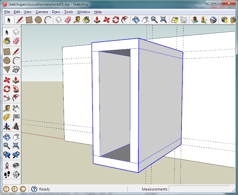
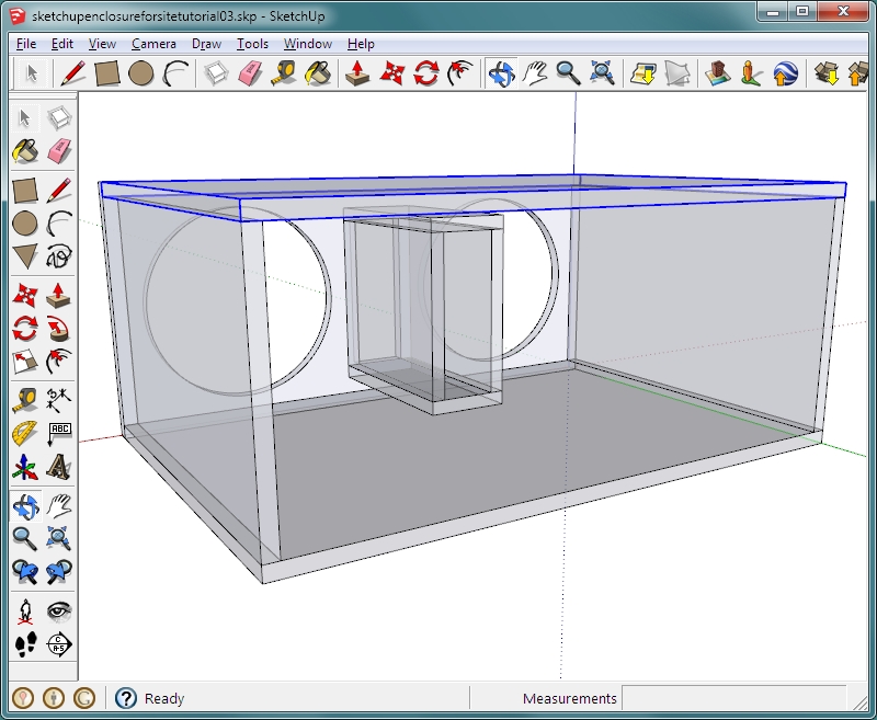
 UN-HIDE all of the parts of the model (EDIT >> UN-HIDE >> ALL). You will see that the back is not the correct size. Delete it (select, delete or use the erase tool). Orbit around so that you see the enclosure from an angle something like the one below. Drag a rectangle from one outside corner of the enclosure to the one diagonally across. Zoom in if you have trouble distinguishing between the inner and outer corners. Use the PUSH/PULL tool to pull it out 0.75". Triple click it and make it a group. Click off of the model to de-select all. Go to VIEW >> GUIDES and de-select it.
 Change the STYLE to x-ray. Orbit around and look at the enclosure.
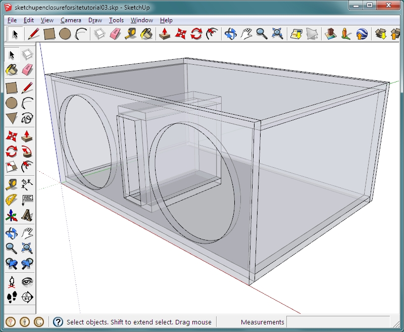 THIS is the file for the final enclosure. This is the end of part 3 of the Sketchup tutorial. Click HERE to go to part 4 (10d in the directory).
|
|
|
|